
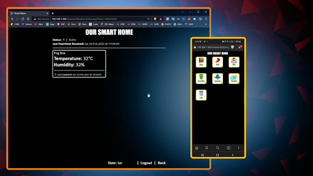
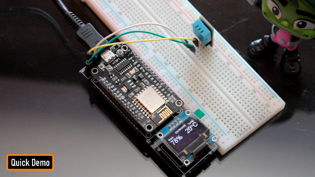
In my last tutorial I created a Weather Station using Arduino and NodeMCU using DHT11 or DHT22 temperature and humidity sensor and displayed it using an OLED Display. In this tutorial, I am going create a Peg-Box using the same board but with a little bit of twist. In this setup, I am going to send the Temperature and Humidity readings to my Raspberry Pi based home server and store it in a MySQL database. The data can then be viewed using PHP and Google Charts, on a Mobile Phone or a PC connected to the home network.
Sponsors

This video is sponsored by PCBWay.

PCBway: only $5 for 10 pcbs from https://www.pcbway.com/?from=CZcouple
PCBWay specialize in manufacturing of very high quality, low-volume, colored PCBs at a very budgetary price. In addition to the standard PCBs, you can also order Advanced PCBs, Aluminum PCBs, FPC/Rigid-flex PCBs. They also provide PCB assembly and other related service which can meet your needs to the greatest extent.
The ordering process from PCBWay is very easy. Once I had my design ready, I just had to upload the gerber file to the PCBWay's website and select the type, color and any other customization that I want and then just send it for fabrication.
For my project, I choose the black color. PCBWay ships from china to most of the countries of the world within 3 to 7 business days. Talking about the quality, its absolutely mind-blowing.
Circuit Diagram

The setup is very simple. The temperature and humidity sensor sends the collected data to the NodeMCU on pin D3. NodeMCU then sends the data over WiFi to the Raspberry Pi, which is then saved in the MySQL database.
The Yellow LED, which is the status indicator flashes every second and is connected to D6 pin of the NodeMCU. The Blue LED connected to pin D5, lights up when NodeMCU sends the temperature and humidity readings to the database.
If you are planning to install this box somewhere inside the house, then you can also add an OLED display and display the readings on it.
The Board

So, this is how my board looks like in 2d and 3d.
There are 3 breakout boards in this 100cm x 100cm assembly. Each board can be used with either Arduino or NodeMCU and DHT11 or DHT22 sensor or sensor module.
Temperature and humidity readings can be collected using either a DHT11 or DHT22 Module or by using one of these sensors with a 10K resistor.
The bottom section of the board is for the OLED display. The attached gerber is bit different from what you see on screen. I made some modifications in the final version and moved the sensors a bit far from the microcontrollers.
Component Assembly

Lets start by soldering the female pin-headers to the board. The pin-headers will house the NodeMCU in it.
Next, lets soldered few more pin-headers for the LEDs, DHT11 sensor and the OLED display.
Before installing the circuit in the peg-box, lets hook up the OLED Display and make sure everything works as expected. Boom, nailed it.
The Code

The code starts by including all the libraries and by defining all the constants and variables that will be used throughout the program.
Then there are two functions SendIamAlive() and SendTemperatureAndHumidity() which sends heartbeat and the data read from the temperature sensor to the database server.
The ReadDHTSensor() function reads the data from the DHT11 or DHT22 sensor.
In the setup section we first setup the WiFi and then send a SendIamAlive() message to the server advising that it is back up and running. Then in the loop section the microcontroller send a heartbeat every minute using the SendIamAlive() function and if the time elapses it sends the humidity and temperature data using the SendTemperatureAndHumidity() function.
The White LED flashes every seconds and the Blue LED turns on when the device sends the temperature and humidity data to the database server.
MySQL

So,the data sent by the NodeMCU over WiFi is saved in the MySQL database hosted on a RaspberryPi 4.
Here you can see, the microcontroller sends the data every 30 minutes (you can change the frequency) which is then saved in the MySQL database. The data saved on the Pi's MySQL database can then be used to generate various different types of graphs either by using google charts or any other 3rd party application. It totally depends on you how you want to present it.
3D Design

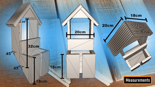
Now, lets look at the design of the peg-box. Using freely available pallet planks, I designed the body of the box.
The pallet planks I am using are 160cm x 9cm x 2cm (length, width and thickness). So, the rest of the measurements will be based on that.
The top bit of the peg-box will house the microcontroller and the sensors in it. Putting it on the top prevents the electronics from adverse climatic conditions.
The back bit will stick to wall and hence we don't need to cover it up.
You can either put the pegs straight in the front bin or throw it to the top bit, from where it will slide down to the front bin.
The sliding design with an opening in the front will prevent rainwater from accumulating inside the bin. This mechanism will keep the bin dry throughout the year.
Woodworking

Using 2 hammers I am dismantling the pallet. My aim is to reuse all the nails used in building this pallet so that, I can use them in building my project. After that, I sanded the pallet planks to give them a nice and smooth texture.
Then using a chop-saw or a hand-saw I extracted all the pieces of wood required for building this project.
As mentioned earlier, my pallet plank are 9cm wide and hence, all the onscreen measurements are based on that.
Final Assembly
I got a bit too excited and accidentally deleted one of my recordings. So, I am using 3D animation to show you guys how I joined the two sides of the box.
I used a plywood board to created the base of the bin.
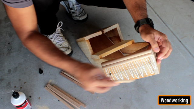
I glued few cylindrical wooden sticks on the roof of the box. To be very frank these sticks changed the entire outlook of the peg-box.
Coloring
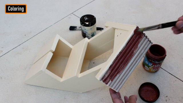
Since my aim is to install the peg-box outside the house, I have to make sure that I apply multiple coats of paint on the box to avoid the pallet wood from rotting. I applied 3 coats of paint on the entire setup and insulated all the holes that I found using wood putty.
So, this is how it looks like. The electronics bit will stay hidden under the roof of the box. Ha ha, Don't worry, I will obviously insulate them and make them weather-proof before installing them on the wall.
Installation
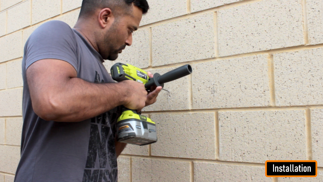
Now the next thing you need to do is to find a spot where you want to install this unit.
I am installing this near my clothesline, however you may want to install it in your pantry or behind a door or something like that. It totally depends on how much space you have and where you want to install it.
I am using metal frame hangers to hang this on the wall.
Place the unit against the wall, and using a pencil mark the points where you want to drilling the holes.
Now, using a hammer drill, drill the holes in the wall.
Then, put the wall plugs in the wall and then use a screw driver to install the screws.
Alright so, that's it. This unit is now all set to hold all my pegs in it.
Demo

So, this how my final setup looks like. Do comment and let me know if there are any scopes of improvement.
Thanks
Thanks again for checking my post. I hope it helps you.
If you want to support me subscribe to my YouTube Channel: https://www.youtube.com/user/tarantula3
Blog Posts:
1. Peg Box
Video references:
1. Peg Box
Resources:
Code:
Libraries:
Support My Work:
BTC: 1M1PdxVxSTPLoMK91XnvEPksVuAa4J4dDp
LTC: MQFkVkWimYngMwp5SMuSbMP4ADStjysstm
DOGE: DDe7Fws24zf7acZevoT8uERnmisiHwR5st
ETH: 0x939aa4e13ecb4b46663c8017986abc0d204cde60
BAT: 0x939aa4e13ecb4b46663c8017986abc0d204cde60
LBC: bZ8ANEJFsd2MNFfpoxBhtFNPboh7PmD7M2
Thanks, ca again in my next tutorial.


No comments