A sensor is a device that detects and responds to inputs from the physical environment. The input can be light, heat, motion, moisture, pressure, or any other environmental phenomena. Sensors are very important part of electronics, especially in Robotics and Automations. The output generated by the sensors are transmitted to other circuits for reading or for further processing. They make our life easy by automatically sensing and controlling devices, without human interaction. In this video, we are going to talk about "IR sensors" or Infrared sensors, how they work and how to build a "DIY IR Sensor Module".
Sponsor
----------

This video is sponsored by PCBWay.
PCBway: only $5 for 10 pcbs from https://www.pcbway.com/
PCBWay specialize in manufacturing of very high quality, low-volume, colored PCBs at a very budgetary price. In addition to the standard PCBs, you can also order Advanced PCBs, Aluminum PCBs, FPC/Rigid-flex PCBs. They also provide PCB assembly and other related service which can meet your needs to the greatest extent.
Thousand of engineers, students and hobbyists worldwide are using their PCBs for their daily work and study.
When you signup with PCBWay, you get $5 credit and with every order you place you get "beans" which you can redeem for products and services.
The ordering process from PCBWay is very easy. Once I had my design ready, I just had to upload the gerber file to the PCBWay's website and select the type, color and any other customization that I want and then just send it for fabrication.
For my project, I choose the black color. PCBWay ships from china to most of the countries of the world within 3 to 7 business days. Talking about the quality, its absolutely mind-blowing.
Components Used
-----------------------

For this project we need:
- 1 x LM358 IC
- 1 x 10K Potentiometer
- 1 x LED
- 1 x IR LED
- 1 x PhotoDiode
- 1 x 100Ω Resistor
- 1 x 100kΩ Resistor
- 1 x 220Ω Resistor
IR LED
-----------
Now lets talk about the three main components of this module:
1. IR Transmitter [IR LED]-----------------------------------

The IR LED (Infrared Light-Emitting Diode) is a SSL (Solid State Light) emitting diode that emits light with a longer wavelengths than the visible light. (The frequency range of infrared is higher than microwave and lesser than visible light). IR light is invisible to human eyes as its wavelength ranges between 700nm to 1mm. Everything which produce heat, emits infrared light, a very common example is the human body and fire. Infrared light has the same properties as the visible light, it can be focused, reflected and polarized.The appearance and operation of an IR LED is same as a common LED. When operated at 5V, the IR transmitter consumes about 3 to 5 mA of current. Depending upon the Transmitter and Manufacturer, IR LEDs can have light emitting angle of approx. 20-60 degree and range of approx. few centimeters to several ft (Some transmitters have the range in kilometers).Since the human eye cannot see the infrared radiations, it is not possible for a person to identify if an IR LED is working or not. The simplest way to view infrared light is by using a remote control while looking through a camera. If the infrared LED is working, it will appear on the digital camera's viewfinder as a purple glow.Unlike LEDs that project parts of the visible light spectrum, IR LEDs are not used to provide lighting. They are, instead, most commonly used in various signal transferring systems, such as in remote controls, night-vision cameras and other devices.IR LED’s are commonly used in conjunction with the IR receiver to support a wireless communication between 2 or more devices.
2. IR Receiver [PhotoDiode]------------------------------------

A photodiode is a semiconductor device that converts light into an electrical current. The current is generated when photons are absorbed by the photodiode similar to a Light Dependent Resistor (LDR), means it has very High Resistance in absence of light and the Resistance become low when light falls on it. However, unlike the LDR which is analogue and bidirectional, Photodiode is a unidirectional semiconductor which has a P-N junction and operates in Reverse Bias (means it start conducting the current in reverse direction when Light falls on it). Photodiodes can only do two values: either on or off.
Photodiodes also looks like a LED, with a Black color coating on its outer surface.Different types of IR receivers exist based on the wavelength, voltage, package, etc. When used in an infrared transmitter – receiver combination, the wavelength of the receiver should match that of the transmitter.
3. LM358 IC----------------

LM358 is a dual operational amplifier (Op-Amp) IC, integrated with two op-amps powered by a common power supply. In this circuit we are using it as a voltage comparator.The LM358 has two independent voltage comparators inside it, which can be powered by single pin, so we can actually build two IR sensor modules using this IC. In this tutorial I will only use one comparator, which have inputs at PIN 2 and 3 and output at PIN 1.The voltage comparator has two inputs, one is inverting input (PIN 2) and second is non-inverting or in-phase input (PIN 3). When voltage at non-inverting input (positive pin) is higher than the voltage at inverting input (negative pin), then the output of comparator (PIN 1) is High. And if the voltage of inverting input (negative pin) is Higher than non-inverting end (positive pin), then output is LOW.PIN 4 is the negative power supply (when dual power supply operates) or ground (when single power supply operates). PIN 8 is the positive power supply; Pins 1, 2, and 3 are one op-amp channel, and pins 5, 6, and 7 are the 2nd op-amp channel.
LM358 Datasheet: Download File
Principle of Working
---------------------------

An IR sensor consists of an IR LED and a Photodiode (together they are called as Opto–Coupler or Photo–Coupler). IR sensor work on the principal in which IR LED emits infrared radiation and Photodiode sense that radiation. Photodiode's resistance changes according to the amount of IR radiation falling on it, hence the voltage drop across it also changes and by using a voltage comparator (like LM358) we can sense the voltage change and generate the output accordingly.
We can place IR LED and Photodiode in two different ways:
1. Direct and
2. Indirect
In Direct incidence, IR LED and photodiode are placed facing each other, so the IR radiation directly falls on the photodiode. When an object is placed between the IR pair, it stops the falling of IR light on the photodiode.
And in Indirect Incidence, both IR LED and Photo diode are placed side by side (in parallel both facing the same direction). When an object is placed in front of IR pair, the IR light gets reflected by the object and gets absorbed by photodiode.
Schema
----------
Basically, an IR Module is a combination of a IR transmitter and receiver circuit.
Infrared light emitted by the IR LED is detected by the Photodiode. LM358 Op–Amp IC is used as a voltage comparator. Voltage at inverting end, which is also called "Threshold Voltage", can be set by rotating the potentiometer.
When we turn ON the circuit there is no IR radiation towards photodiode and the Output of the comparator is LOW. By placing an object in front of IR pair, we reflect the IR light which is absorbed by the photodiode and the voltage across photodiode drops, and the voltage across series resistor R2 increases. When the voltage at Resistor R2 (which is connected to the non-inverting end of comparator) gets higher than the voltage at inverting end, then the output becomes HIGH and LED turns ON.
Voltage at inverting end, can be set by rotating the variable resistor’s knob. Higher the voltage at inverting end (-), less sensitive the sensor and Lower the voltage at inverting end (-), more sensitive the sensor. The threshold voltage can be adjusted by adjusting the potentiometer depending on the environmental conditions.
The Board
-------------

So, this is how my board looks like in 2D and 3D.
There are 15 individual IR Modules on this 100cm x 100cm board.
Gerber : Download File
Assembly
------------
Lets start the project by soldering the 3 resistors to the board.
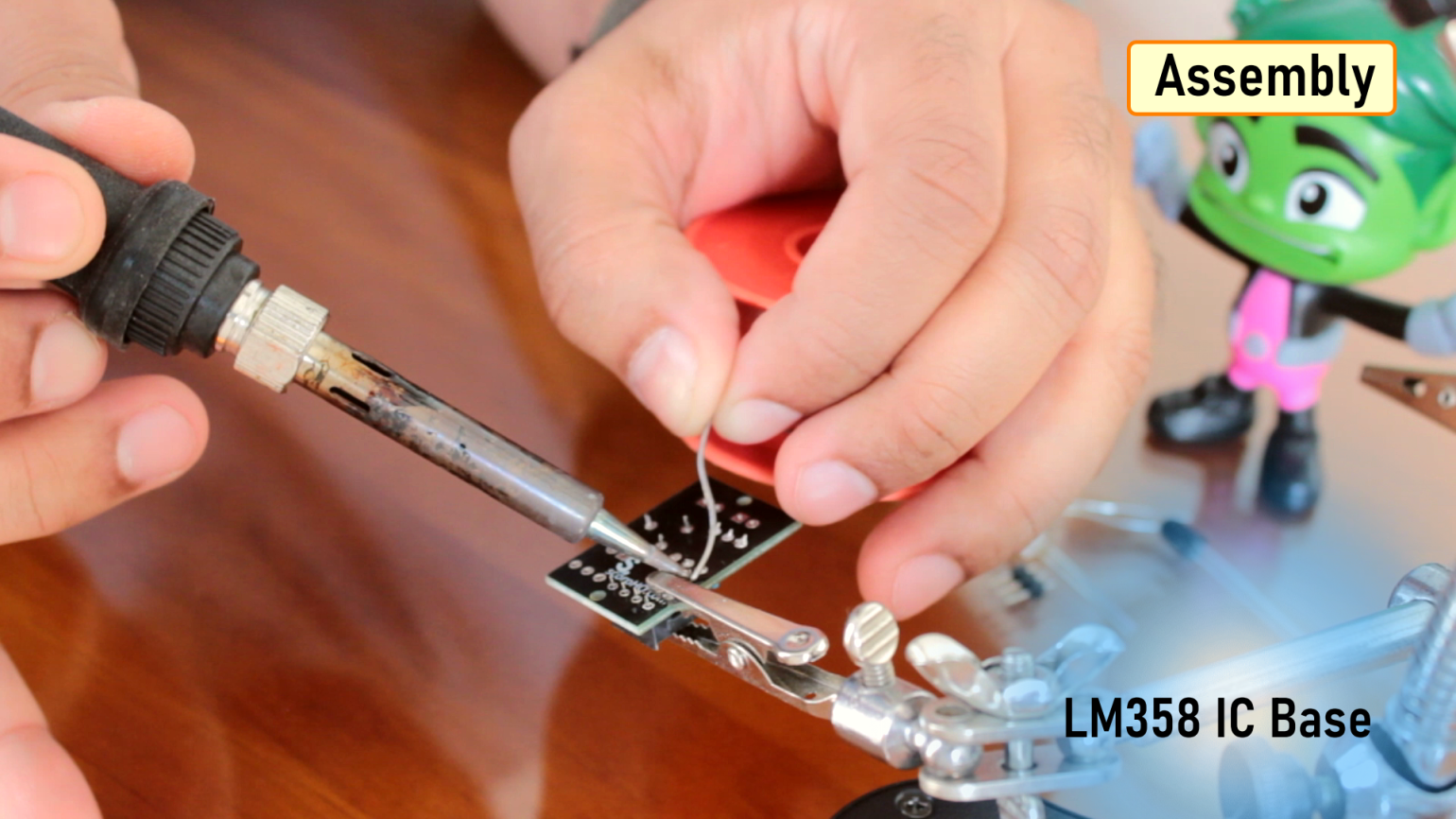
After that, I am soldering the 10K pot followed by the base of the LM358 IC.
Next, I am soldering the male pin header to the board.
After that, I am soldering the optional LED indicator to the board. If you don't want the LED indicator then you can skip the 220Ω Resistor which we installed in Step 1.
Next, I am soldering the photodiode and the IR LED to the board.
Now, to finalize the setup I am installing the LM358 IC to the base which we soldered in Step 3, that's it all done.
Demo
-------

By placing my hand infront of the IR module I am reflecting the infrared light emitted by the IR LED towards the PhotoDiode. The PhotoDiode detects the light and turns the output of comparator PIN-1 to High. When the output at Pin-1 goes HIGH the LED indicator lights up.
By adjusting the resistance of the potentiometer we can control the sensitivity of the phototransistor.
Areas of Application
--------------------------

The IR sensor is a very popular sensor, which is used in many applications in electronics, like:
• Remote controls
• Motion detectors
• Obstacle detectors
• Product counters
• Line following robots
• Alarms
• Audio equipment
• Lighting equipment
• Night vision cameras
• To distinguishing between black and white colors
• Signal transfer systems
• For machine to machine communication and more...
Types of IR LEDs categorized by the wavelength:
• Near infrared region — 700 nm to 1400 nm
• 808 nm – suitable for medical treatments, space optical communication, infrared illumination
• 830 nm – suitable for automated card reader systems
• 850 nm – suitable for night vision cameras, CCTV monitoring systems, digital photography
• 940 nm – suitable for remote controllers
• Mid infrared region — 1400 nm to 3000 nm — Heat sensing
• Far infrared region — 3000 nm to 1 mm — Thermal imaging
Advantages and Disadvantages
-----------------------------------------

Advantages:
• Infrared devices can detect soft objects which may not be easily detected by ultrasonic sensors
• They provides secured communication due to line of sight or point-to-point mode of communication
• They consume very low power to operate
• They are very small and inexpensive
• They provides good stability over time
• No corrosion or oxidation can affect the accuracy of infrared sensors
• They delivers high repeatability
Disadvantages:
• Infrared frequencies are affected by hard objects like walls, smoke, dust, fog, sunlight etc. Hence it does not work through walls or doors.
• Infrared waves at high power can damage eyes
• Objects shouldn’t be black as it will absorb all the IR light
• They require Line of Sight between transmitter and receiver to communicate
• They can control only one device at a time
• They supports shorter range and hence their performance degrades as the distance increases
• They supports lower data rate transmission as compare to wired transmission
Thanks
--------
Thanks again for checking my post. I hope it helps you.
If you want to support me subscribe to my YouTube Channel: https://www.youtube.com/user/tarantula3
Video: https://www.youtube.com/watch?v=_M8FQIPi1qk
Full Blog Post: https://diyfactory007.blogspot.com/2020/10/diy-ir-module.html
Gerber File: https://drive.google.com/file/d/1mmgJSyBvGcu06svoI5GWUhi9RXikFYVA/view?usp=sharing
LM358 Datasheet: https://drive.google.com/file/d/1xB7Pk_Mp4StcMPGTS2LTl527Tr1VT-Yb/view?usp=sharing
BTC: 35ciN1Z49Y1bReX2U7Etd9hGPWzzzk8TzF
DOGE: DDe7Fws24zf7acZevoT8uERnmisiHwR5st
LTC: MQFkVkWimYngMwp5SMuSbMP4ADStjysstm
ETH: 0x939aa4e13ecb4b46663c8017986abc0d204cde60
BAT: 0x939aa4e13ecb4b46663c8017986abc0d204cde60
Thanks, ca again in my next tutorial.
Tags
------
IR LED, IR Sensor, PhotoDiode, DIY IR Module, How IR Module works, LM358, voltage comparator, lm358 circuit, all about ir sensor,


No comments:
Post a Comment